It’s not a DeLorean, a Tunnel, or a British phone booth, but a data recorder is a time machine. Most people don’t realize it, but they actually use time machines every day. They come in all different flavors. Most time machines are consumer-oriented and exist in the form of cameras, voice mail, and video recorders.
Each of the recordings created by these devices represents an instance, or a period of time, and place in the past. A photo represents a single instance while a video or voicemail represents an event that spans a period of time. When people review these recordings, they are looking back in time.
Most recorders, particularly those that are consumer oriented, can reproduce what was recorded in a form that closely represents what was originally captured. For instance, a digital picture wouldn’t be useful if it was presented as a series of bits and bytes. To be useful, the bits and bytes are interpreted into pixels that are arranged to represent what was originally captured.
However, not all applications require reproduction in exactly the same form or in the same physical time span. A PCI Express bus tracer, for example, would generally be useless to an engineer if the recording simply re-drove signals to a PCIe bus as they were originally captured. For this application, the recorded data is processed and “reproduced” as a graphical display that shows a series of time-stamped PCIe transactions. Though not reproduced at the original speed or physically the same way, the graphical representation again allows the user to look back in time and locate the problem.
While the number of applications for a data recorder is endless, a very short list includes SIGINT, RADAR, Electronic Warfare, Imaging, Protocol/Logic Analysis, Self-Driving Cars, Aerial Mapping, and Simulation.
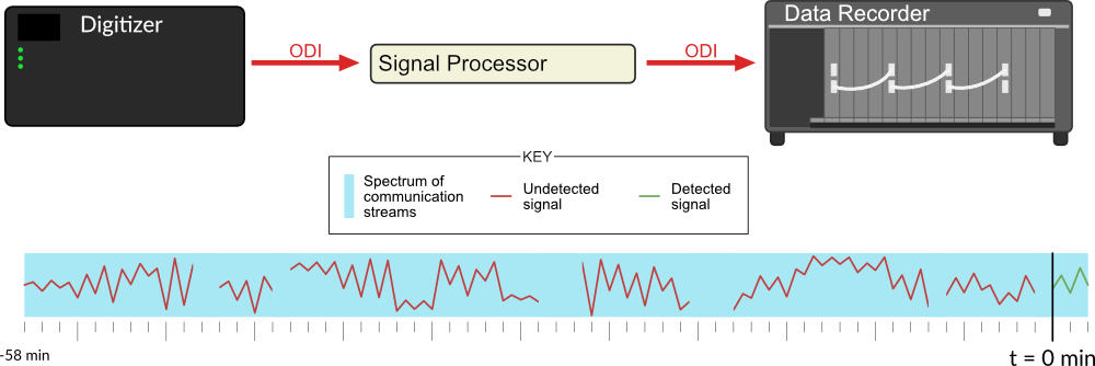
When applied to SIGINT (Signal Intelligence), for example, one objective may be to detect and capture enemy communications. Referring to Figure 1, many different communication streams and different types of communication can occur simultaneously within a wide spectrum. In addition, a single communication might hop across multiple frequencies to deliberately make it difficult to intercept. A high-speed digitizer can capture a wide bandwidth of RF communications in a single data stream which is then passed along to an in-line real-time signal processor. This processor will attempt to detect enemy communications. However, it is possible that a signal of interest may not initially be detected until later in time. If the digitized spectrum was not stored on a data recorder then the early parts of the enemy communication will be lost forever. There will be no ability to go back in time and review it.
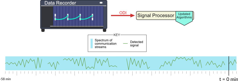
Used as a simulation device, a data recorder can be pre-filled with a theoretical waveform and played back through a signal processor or to a waveform generator. In the previous example, the actual recorded spectrum could be repeatedly played back (Figure 2) through a signal processor (hardware or software) until the algorithms have been successfully modified so that they would have detected the previously undetected signal.
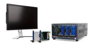
Many of the instrumentation devices today are self-contained (single box), constrained to a limited set of functions, and do not significantly collaborate with other instruments. Modular instruments such as those of AXIe and PXIe chassis types significantly improve the ability of different instruments to work together. Since they are controlled by the same computer, each instrument can connect data streams between cards with backplane local busses, and can pass inter-card triggers. However, the data path interconnections between instruments may be limited both in bandwidth and distance due to their copper connections.
The AXIe Consortium recently introduced the ODI (Optical Data Interface) standard. This standard defines a high-speed optical interface that moves data between instruments and embedded systems at rates currently up to 160Gb/s per connection. New products that support ODI include, but are not limited to, digitizers, signal processors, waveform generators, and data recorders. ODI interfaces can be incorporated in both standalone and modular products resulting in the following benefits:
- Standalone instruments can now collaborate with other instruments on the same high-speed data stream.
- Modular products, such as those for AXIe or PXIe, retain their inherent benefits while being able to pass data at higher rates between slots.
- High speed streams can be shared between instruments over much longer distances.
- Instruments of different formats (AXIe, PXIe, standalone) can be interconnected.
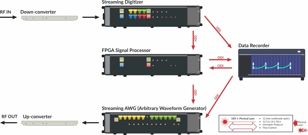
Applied to the above SIGINT example (Figure 3), a 16GSa/s digitizer with 10-bit sampling produces a 160 Gb/s ODI data stream of data with an analog bandwidth of 6.5GHz. Similarly, a 32GSa/s digitizer can output a pair of 160 Gb/s ODI streams with an analog bandwidth of 12.5GHz. If real-time processing is needed the digitizer ODI output ports would connect to an ODI-capable signal processor. The signal processor could take the form of an ODI-connected FPGA board that allows the user to insert custom code into the FPGA(s). If data recording is needed, then one or more data recorders can be connected to the signal processor or digitizer ODI output(s). If post-recording signal processing or waveform reproduction is needed, then the recorder ODI output can be connected to the processor or waveform generator ODI inputs, as needed, and the spectrum can be played back at the same speed it was recorded.
The amount of storage in the data recorder determines the size of the time window that can be stored. A 160Gb/s data stream stores a terabyte of data every 50 seconds. Thus, an 8TB recorder could store data for just under 7 minutes while a 64TB recorder could store data for just over 50 minutes, and so on. Where only a portion of the spectrum is of interest, the available recording time may be increased through the use of DDC (Digital Down Conversion) techniques. DDC allows one to remove portions of the spectrum from the digital data stream thus lowering the data stream bit rate and increasing the available recording time for a given amount of storage.
Time machines can also save money by improving time-to-market. Suppose the engineer is trying to locate a difficult-to-identify design bug that is highly intermittent and is delaying a new product introduction. As can be the case in digital electronics, the incident error event might not manifest itself as a failure until some point later in time. Many instruments may detect the later manifestation but not the incident error itself. These instruments often won’t have sufficient storage to look back far enough in time to expose the incident error. A data recorder with enough storage can provide a “first-time-every-time” capture of the highly intermittent incident event. While there may be a lot of data to sift through electronically, the answer will be in the recording if the correct information was recorded. For design bugs where time is of the essence, the ROI (Return On Investment) in a time machine may be immediate and substantial.
Leaders in the instrumentation industry have implemented ODI in their latest generation of products. The critical addition of a high-speed ODI-connected data-recording device enables new capabilities and opportunities for researchers, product developers, and defense-related activities. It’s only a matter of time!