 Xilinx® produces several development boards with PCI Express and optical interfaces that can be used for various user-defined applications. Some Xilinx development applications may produce a high-speed stream of data to be recorded while others may require the injection of a continuous-speed data stream.
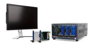
Conduant StreamStor® can record or play back real-time data streams at rates up to 20 GB/s (160 Gb/s or 1 Terabyte every 50 seconds) regardless of the type of data (RF, RADAR, imaging, etc.). StreamStor® can connect optically or with copper wires through its high-speed serial interface lanes. This application note focuses on the optical connection. Since StreamStor® products are designed with Xilinx FPGAs, they are highly configurable and easily interface with Xilinx development boards or other Xilinx-based designs.
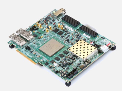
Almost any Xilinx development board that has high-speed serial optical lanes can connect with StreamStor® using one of many different protocols (Aurora, Interlaken, Serial RapidIO, etc.). For the purposes of this article, however, the Xilinx VCU118 (Figure 1) was chosen to demonstrate interconnections because it has both QSFP28 (4-lane, 8-fiber) and Samtec FireFly™ Micro Flyover System™ (4-lane, 8-fiber) interconnect options.
The Conduant Cobra board (Figure 2) provides the optical interface to the StreamStor® recorder (Figure 3). The Samtec FireFly™ Optical cable assembly on Cobra delivers 12-lane connectivity through a 24-fiber MTP/MPO connector. The differences in types of transceiver modules and lane-widths between Cobra and the VCU118 board provide an ideal example for demonstrating various ways to optically connect to StreamStor®.
This application note will show:
- It is easy to add a StreamStor® recorder/player to a Xilinx development board.
- A method of adjusting between endpoints of different lane widths.
- A method of adjusting between transceivers of different types.
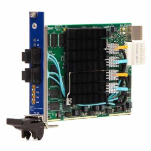
Figure 2. Conduant Cobra FPGA interface card 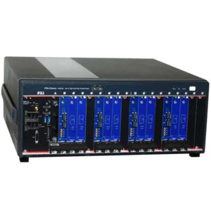
Figure 3. Conduant StreamStor® recording system
Xilinx VCU118 Evaluation Board
The Xilinx VCU118 evaluation board (Figure 1) provides 12 lanes of high-speed serial connectivity that is spread across three groups of four lanes. Two of the three groups connect to QSFP28 pluggable sockets which are located on the rear-panel-end of the board. The remaining 4 lanes are accessed through a socket on the board into which a Samtec FireFly™ 4-lane optical transceiver is inserted.
QSFP28-to-MTP/MPO Optical Transceivers
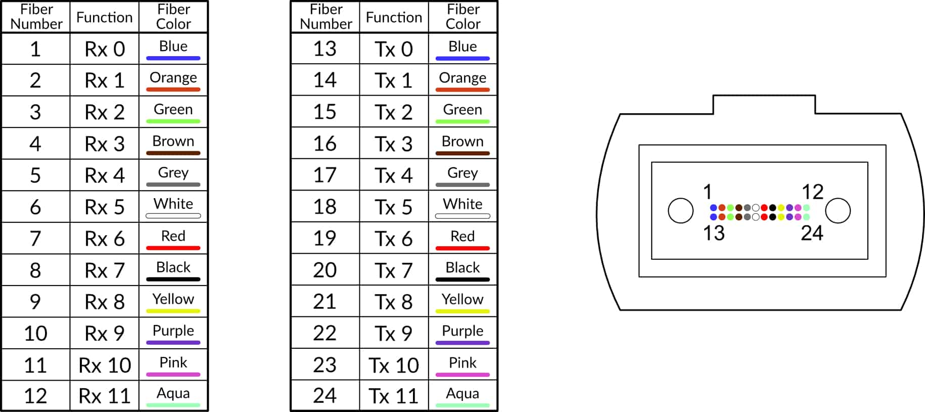
The two QSFP28 sockets can each connect up to 4 lanes (4 transmit and 4 receive) of signaling for a total of 8 lanes. QSFP28 pluggable optical transceiver modules are available that present their 4 lanes (8 fibers) through a 12-fiber (4 fiber ports are unused) MTP/MPO socket. One example of a QSFP28 MTP/MPO transceiver module is the Cisco QSFP-100G-SR4-S (or compatible, Figure 4). See figure 5 for fiber mapping of this module.


Samtec FireFly™ Micro Flyover System™
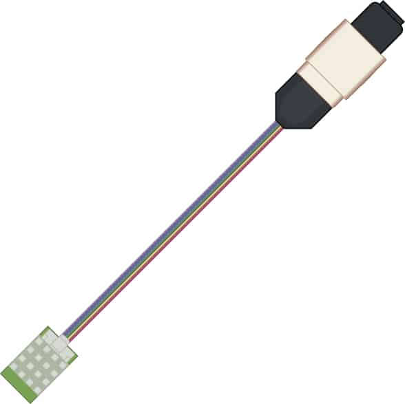
The VCU118 has a single socket on the circuit board to insert a four-lane Samtec FireFly™ optical transceiver (REF-193848-01, Figure 6). The FireFly™ optical transceiver module plugs directly into the socket and provides an 8-fiber “tail” that comes out to a 12-fiber MT ferule. The MT ferule is then mounted into a MTP/MPO adapter (Figure 7) that can be mounted on the endplate of the VCU118 board.
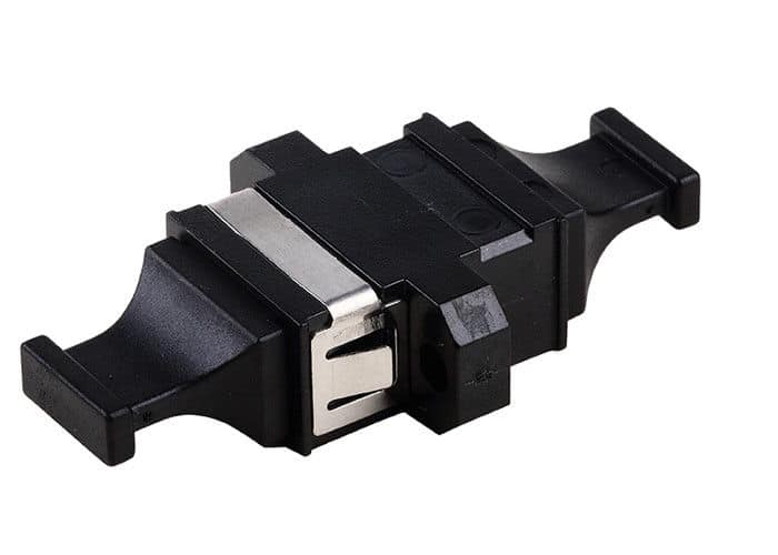
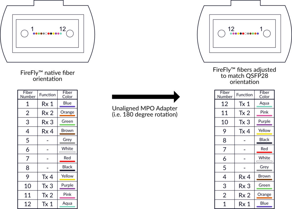
As shown in Figure 8, the native mapping of the four lanes of FireFly™ is opposite that of the QSFP28 MPO signals. In other words, Tx and Rx fibers are end-to-end reversed. For this application, we want the FireFly™ fiber arrangement to match that of the QSFP28 modules. This is accomplished by mounting the FireFly™ MPO male connector in an unaligned adapter such as a Senko 774-K or similar. This adapter reverses the order of the FireFly™ fibers so that its Tx and Rx positions match those of the QSFP28 MPO connectors.
Copper Alternative
Note that the Samtec FireFly™ Micro Flyover System™ and QSFP28 also provide copper cable assembly options (ECUE series) for when copper is desired in lieu of optical, but this option is not shown in this document.
Conduant Cobra Board
24-Fiber MTP/MPO Connectors
The Conduant Cobra board is the hardware engine that manages data flow and optical connectivity for the StreamStor® recorder/player. Its two front-panel MTP/MPO connectors each bring out 12 lanes (12 transmit and 12 receive fibers) that can move data at rates of up to 16.3 Gb/s per lane. Thus the pair of connectors can be used to provide 24 lanes of optical connectivity to a StreamStor® recorder.
When the aggregate record/playback bandwidth is less than or equal to 5 GB/s (40 Gb/s) Cobra can provide up to 24 lanes of connectivity with its two optical connectors. This is useful for applications in which a large number of slower devices must be connected.
When higher bandwidth is needed, rates up to 20 GB/s (160 Gb/s or 1 Terabyte every 50 seconds) are achieved through a single 12-lane port. The remaining 12-lane port is used by Cobra to extend the bandwidth with a connection to additional Cobra boards.
See figure 9 for the signal map of the 24-fiber MTP/MPO connector on Cobra.
Wave2Wave 3-to-1 Optical Adapter Cable
To this point in the document all 4-lane transceiver ports on the VCU118 have been brought out to 12-fiber MTP/MPO connector sockets. The objective now is to connect the three 4-lane ports to a single 12-lane port on the Cobra board. This is accomplished with a Wave2Wave Fiber Patch Cord.
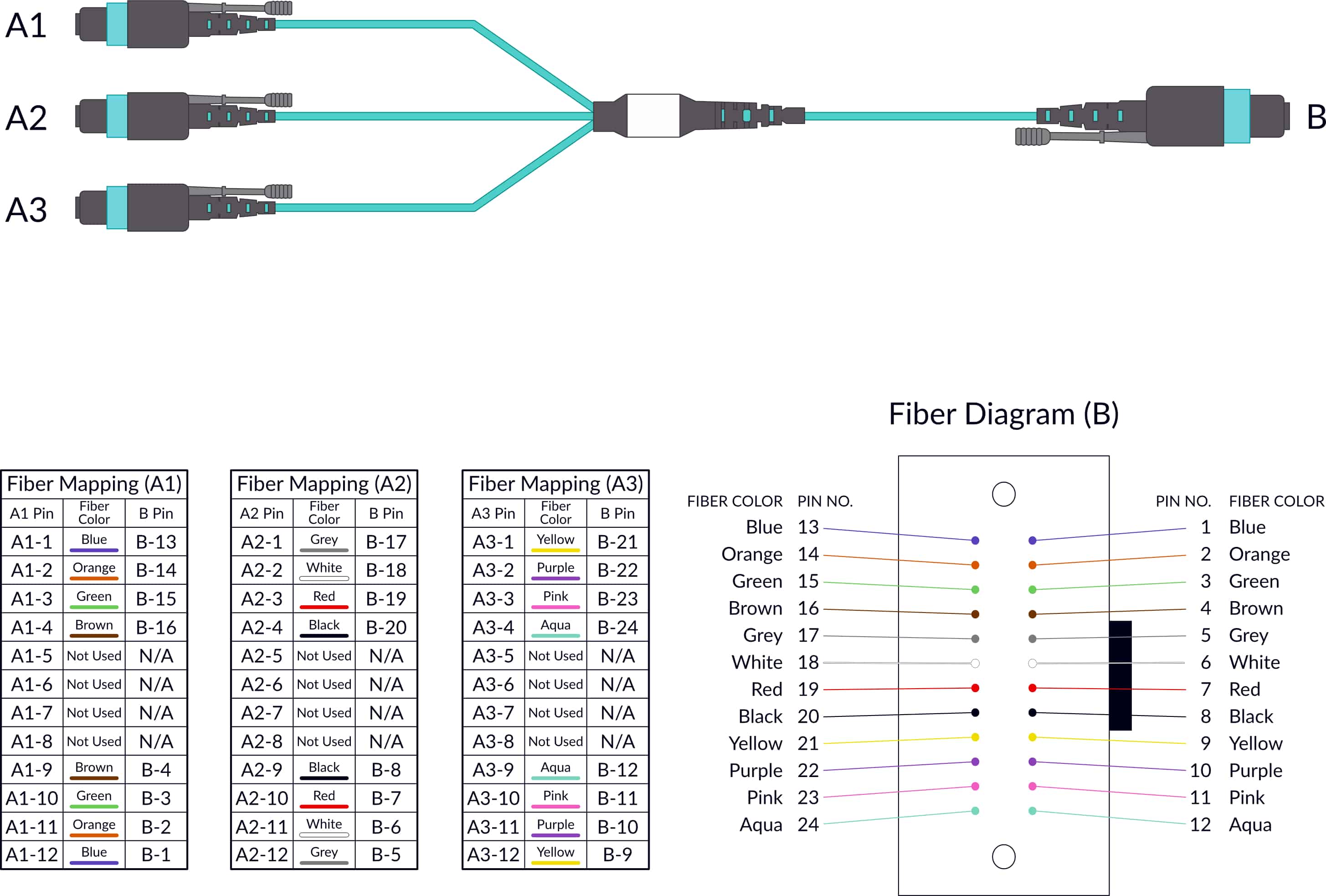
The Wave2Wave Fiber Patch Cord (Figure 10) establishes a 12-lane connection between a 12-lane port on Cobra and three 4-lane ports on the VCU118 board. The cable connects each group of 4 lanes on one end to different groups of 4 lanes in the 12-lane connector thus creating a 12-lane connection between boards. The fiber mapping of this cable is also shown in figure 10.
Pulling It All Together
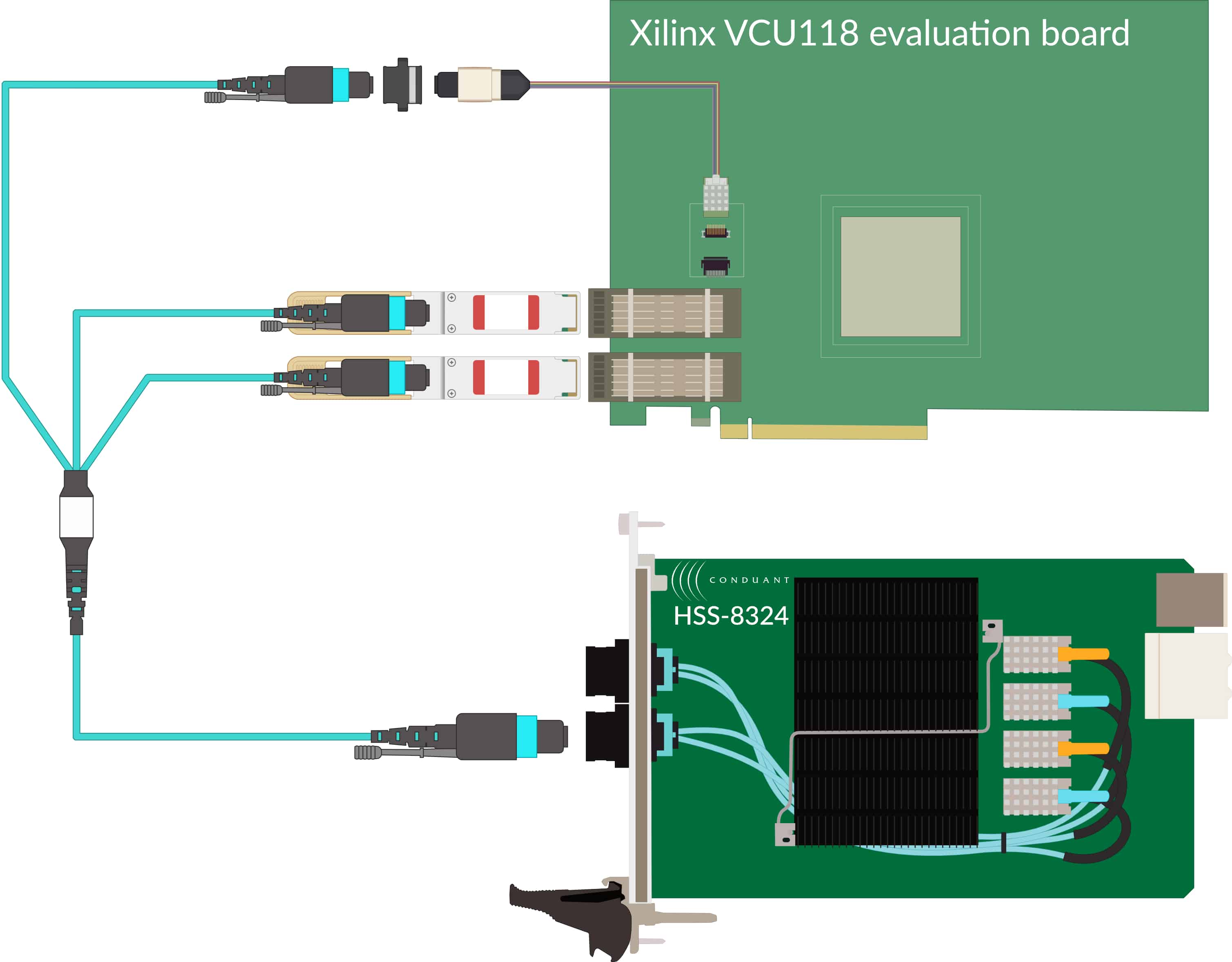
Figure 11 shows a complete optical interconnection of three groups of 4 lanes on the Xilinx VCU118 board to a 12-lane port on a Cobra board.
Other Configuration Possibilities
Many Development Boards to One StreamStor®
While not shown in this document, it is also possible to connect multiple Xilinx development boards to a single StreamStor® Recorder. For instance, the three 4-lane connectors on the patch cord shown above could just as easily connect to a single 4-lane port on each of three different VCU118 signal processing boards. A 12:1 patch cable could connect a single lane from each of 12 VCU118 boards to a single 12-lane MTP/MPO port on a Cobra board. These are just a few examples. Patch cables can be customized by manufacturers as needed for the particular application.
In an extreme configuration, up to 24 signal processing boards (one lane each) could be connected to the two 12-lane MTP/MPO ports on a single Cobra board if the aggregate bandwidth is less than or equal to 5 GB/s (40 Gb/s).
Out-of-Band Signaling
In addition to the high-speed data streams, there may be a need to pass additional signals between a Xilinx development board and StreamStor®. These could be used for communicating triggers or for marking positions in the recording. Conduant Cobra boards provide four MMCX coax connectors on the front panel which could be used for these or other configurable purposes.
Summary
The Conduant StreamStor® Recorder/Player is designed to record and/or play back real-time data streams and is capable of sustaining very high data rates. It is easily optically interfaced with many different Xilinx evaluation boards and is the perfect companion product where this capability is needed.
While the latest StreamStor® is packaged in a PXI Express chassis, this does not preclude the ability to optically connect it to a device of a different form factor. In cases where different form factors or operation in disparate environmental conditions are required, please contact Conduant with specific requirements.